

To build an Arduino-based alarm system, choose an Arduino Uno Rev3 for ample pins and strong community support. Connect PIR motion or magnetic reed sensors to digital inputs, ensuring all devices share a common ground.
Power the board with a regulated 5V supply, and use resistors with LEDs and buzzers wired to digital outputs. Implement debounce logic and timed alerts in code for accurate detection.
Once set, you’ll be ready to explore enhanced features like display integration and wireless notifications.
Key Takeaways
- Select an Arduino Uno Rev3 for sufficient I/O pins, community support, and reliable 5V power options suitable for multiple sensors and outputs.
- Use PIR motion sensors and magnetic reed switches for motion and door detection, wiring sensor outputs to Arduino digital inputs with common ground.
- Connect buzzers and LEDs via digital outputs using current-limiting resistors, and control external sirens or lights through relay modules for high-voltage devices.
- Power the system with a regulated 5V supply, ensure all grounds share a common reference, and use appropriate wire gauges to prevent voltage drops.
- Implement software logic with continuous sensor polling, debounce filtering, and state management to detect triggers and activate alarms reliably.
Choosing the Right Arduino Board for Your Alarm System
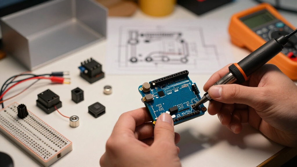
When selecting an Arduino board for your alarm system, you’ll want to prioritize compatibility, ease of use, and sufficient I/O capacity.
The Arduino Uno Rev3 is a solid choice, offering enough digital and analog pins to connect multiple sensors, buzzers, and indicators. Its widespread support and extensive documentation simplify troubleshooting and development.
Make sure the board can handle your sensor inputs and output devices simultaneously without pin conflicts. Consider power requirements; the Uno can be powered via USB or a 5V supply, which suits most prototyping setups.
If you anticipate future expansion, confirm the board supports additional modules like LCDs or relays. Finally, opt for a board with a robust community to access libraries and example code, accelerating your build process efficiently.
Additionally, ensuring your system has reliable backup power can maintain operation during outages, which is critical for security devices.
Sensor Options: Motion, Door, and Proximity
You’ll usually kick things off with PIR motion sensors. They’re great for reliable indoor detection because they’re easy to wire up and you can find them pretty much anywhere.
Now, if you’re looking to keep an eye on doors, magnetic reed switches or Hall-effect sensors are the way to go. They give you direct feedback on whether a door is open or closed, which is super handy.
And hey, if you need something that detects distance as well, ultrasonic sensors can really step up your game. They add that extra layer of proximity detection for when you need triggers that go beyond just motion or door events.
For more precise monitoring, combining PIR sensors with customized Motion Zones can help reduce false alarms and focus detection on relevant areas.
Motion Sensor Choices
Selecting the right motion sensor plays a critical role in defining your alarm system’s effectiveness and reliability.
For most indoor applications, you’ll find the PIR (Passive Infrared) sensor the easiest and most reliable choice. It detects changes in infrared radiation caused by moving heat sources, making it effective for room-scale motion detection.
Wiring is straightforward: connect its digital output to an Arduino input pin and power it with 5V.
Alternatively, ultrasonic sensors measure distance using sound waves, enabling proximity-based motion detection. They require careful placement and calibration to avoid false triggers from static objects.
When choosing, consider detection range, response time, and environmental factors. Keep in mind PIR sensors excel in passive detection without emitting signals, while ultrasonic sensors actively measure distance, which may suit different installation scenarios.
To improve accuracy and reduce false alarms, some systems combine multiple sensor types using dual-technology sensors.
Door And Proximity Sensors
Integrate door and proximity sensors to enhance your alarm system’s ability to detect unauthorized access points accurately. Use magnetic reed switches or Hall-effect sensors paired with magnets on doors or windows to monitor open/close status.
Connect their digital outputs to Arduino input pins, ensuring a shared ground for stable readings. For proximity detection, ultrasonic sensors provide reliable distance measurements, triggering alerts when an object crosses a predefined threshold.
Position them strategically near entryways for optimal coverage. Combine door and proximity sensors with motion sensors to reduce blind spots. Calibrate sensor thresholds carefully in your code to minimize false alarms.
These sensors complement each other by detecting both physical openings and nearby presence. This increases your system’s security effectiveness while maintaining low power consumption and straightforward wiring. For comprehensive safety, consider installing sensors near key living areas to maximize early warnings.
Power Supply and Wiring Best Practices
When powering your Arduino-based alarm system, ensuring a stable and adequate power supply is critical for reliable operation. Use a regulated 5V source, either from the Arduino’s USB input or a dedicated external supply, to prevent voltage fluctuations that could cause resets or sensor errors.
Proper wiring is essential for signal integrity and safety.
Follow these best practices:
- Connect all grounds (Arduino, sensors, actuators) to a common reference point to avoid ground loops.
- Use appropriately rated wires and connectors to handle current without voltage drop or overheating.
- Implement current-limiting resistors for LEDs and verify sensor power requirements to prevent overload.
- Select wires with suitable voltage ratings to ensure safety and compliance with standards.
Connecting Sensors, Buzzers, and LEDs to Arduino
Alright, let’s dive into connecting your sensors, buzzers, and LEDs to the Arduino! First things first, you’ll want to connect the output pins from your sensors to the right input pins on the Arduino. It’s super important to make sure that all your components share a common ground to avoid any issues later on.
Now, when it comes to integrating a buzzer, just pick a digital output pin to control its on and off signals. This will help you generate the sound alerts you need. And don’t forget about those current-limiting resistors when you’re wiring up your LEDs! They’re essential for preventing damage to the LEDs and ensuring they function properly.
Also, to ensure safety and stability in your system, be sure to select the correct gauge power wires and appropriate mounting hardware when connecting multiple components.
Sensor Wiring Basics
Successful sensor wiring hinges on establishing clear, reliable connections between each component and the Arduino. You’ll start by identifying each sensor’s output pin and connect it to the appropriate Arduino input, digital or analog, depending on the sensor type.
Confirm all grounds (GND) from sensors, buzzers, and LEDs share a common reference with the Arduino to avoid erratic readings.
Focus on these essentials:
- Connect sensor VCC to Arduino 5V (or 3.3V if specified) and GND to Arduino GND.
- Attach sensor output pins to designated Arduino input pins, using pull-up or pull-down resistors when required.
- Use current-limiting resistors, typically 220–330Ω, in series with LEDs to prevent damage.
This methodical wiring approach guarantees stable sensor signals, enabling accurate alarm system responses. Always follow a methodical approach and safety when wiring to ensure reliable and safe operation.
Buzzer And LED Integration
After establishing reliable sensor connections, focus shifts to integrating buzzers and LEDs, which serve as the system’s primary alert mechanisms. Connect the buzzer’s positive pin to a digital output on the Arduino and its negative pin to ground.
Use a current-limiting resistor (typically 220–330 ohms) in series with LEDs to prevent damage. Attach LED anodes to separate digital outputs and cathodes to ground. Share a common ground among Arduino, sensors, buzzer, and LEDs to guarantee stable operation.
Program the Arduino to activate the buzzer and illuminate LEDs upon trigger detection, signaling alarm status visually and audibly. This methodical wiring and control approach provides clear, reliable alerts and supports future expansion, such as adding multiple LEDs for different alarm states or integrating external alarm modules via relay control.
For reliable long-term performance, ensure all components share a common ground connection to prevent signal interference and power inconsistencies.
Coding Detection and Alarm Alerts on Arduino
When coding detection and alarm alerts on an Arduino, you’ll need to write efficient routines that continuously monitor sensor inputs and trigger outputs based on defined conditions.
Start by reading sensor states: digital for reed switches or PIR sensors, analog for ultrasonic distances. Use conditional statements to evaluate triggers, ensuring debounce or noise filtering is implemented. Once a trigger is confirmed, activate your buzzer and LED indicators promptly.
Follow these steps:
- Poll sensors regularly in the loop() function with minimal delay to maintain responsiveness.
- Implement state variables to track alarm status (armed, triggered, reset) for controlled output behavior.
- Use non-blocking code techniques (e.g., millis() timing) to handle alert durations without freezing detection.
This approach guarantees reliable, real-time detection and alarm signaling on your Arduino. For enhanced safety, consider integrating interconnected alarm systems to ensure simultaneous alerts across multiple units.
How to Arm and Disarm Using Keypads and Buttons?
To arm and disarm your Arduino-based alarm system effectively, you’ll integrate keypads or pushbuttons as primary user inputs. Keypads enable PIN-based control, adding security by requiring a code to toggle system state.
Pushbuttons provide a simpler, manual way to arm or disarm without code entry. Connect keypad rows and columns to Arduino digital pins and implement debounce logic for reliable input reading. For pushbuttons, use pull-up or pull-down resistors to stabilize the input signal.
Your Arduino sketch should verify input sequences and update the armed status accordingly. It is important to select and activate appropriate operation mode to ensure the system behaves as intended during arming and disarming.
| Input Device | Function |
|---|---|
| Keypad | Enter PIN to arm/disarm |
| Pushbutton | Single press toggle |
| Arduino Pins | Digital I/O for input |
| Logic | Debounce and verify |
Testing Alarm Detection and Response Accuracy
Making sure your Arduino-based alarm system accurately detects triggers and responds appropriately requires systematic testing of each sensor and output component.
Start by verifying sensor input signals under controlled conditions. For example, simulate door openings for reed switches or move within the PIR sensor’s range.
Then, confirm that the Arduino reads these inputs correctly via the serial monitor or debug LEDs. Finally, guarantee the alarm output triggers as expected, activating buzzers and LED indicators promptly.
Follow this methodical approach:
- Test each sensor independently to confirm reliable detection and proper signal levels.
- Validate the Arduino’s input processing logic by monitoring state changes on the serial interface.
- Trigger the alarm output and measure response time and correctness of audible and visual alerts.
This structured testing guarantees precise detection and dependable alarm activation.
Adding Advanced Features: LCD Displays and Remote Controls
You know, enhancing system interaction is really exciting! By integrating an LCD display, you can show real-time status and alert messages right at your fingertips. It’s super handy for checking everything at a glance.
And let’s not forget about the IR remote control! With this addition, you can wirelessly arm or disarm the alarm, which is just so convenient. Plus, the best part? You can achieve all this with minimal changes to your hardware.
These nifty features really boost usability while keeping the wiring and coding straightforward. It’s a win-win!
Integrating LCD Status Displays
Enhance your Arduino alarm system by integrating an LCD display to provide clear, real-time status updates and alarm messages. An LCD lets you monitor system states directly, improving user interaction and troubleshooting.
To implement this, connect a 16×2 LCD module via I2C or parallel pins to reduce wiring complexity and free Arduino pins.
Use the LiquidCrystal or LiquidCrystal_I2C library to initialize and control the display, updating messages based on sensor input and system events.
Program distinct messages for states such as “Armed,” “Disarmed,” “Motion Detected,” or “Door Open,” refreshing the display promptly upon state changes.
This methodical approach guarantees your alarm system communicates its status visually, enhancing usability and situational awareness without increasing hardware complexity.
Using IR Remote Controls
To expand control options for your Arduino alarm system, integrating an IR remote lets you arm, disarm, or trigger alerts wirelessly with minimal wiring changes.
Start by connecting an IR receiver module’s output to a digital input pin on your Arduino. Use an IR remote library (such as IRremote) to decode incoming signals.
Map specific remote buttons to functions like arming, disarming, or triggering the alarm. Make sure you implement debounce logic and state validation to prevent false triggers.
This method reduces physical interface complexity while maintaining secure control. Combine IR control with your existing sensor and buzzer wiring by sharing the common ground.
Finally, test each command thoroughly to verify reliable remote response and proper alarm state transition. This enhances user convenience without compromising system robustness.
Troubleshooting Common Arduino Alarm Issues
When an Arduino-based alarm system malfunctions, you should systematically verify each component and connection to isolate the issue.
Begin by checking your power supply to ascertain the Arduino and sensors receive stable voltage.
Then, inspect wiring for loose or incorrect connections, especially at sensor input pins and buzzer outputs.
Finally, review your code to confirm sensor readings trigger alerts correctly.
Follow these steps:
- Test sensors individually with the Arduino’s serial monitor to verify output signals.
- Measure voltage at critical points, such as sensor VCC and buzzer pins, to confirm proper power delivery.
- Use simple sketch versions to isolate code problems, focusing on sensor input and alarm output logic.
This methodical approach helps pinpoint faults efficiently without introducing guesswork.
Expanding Your Alarm System With Wireless and Relay Modules
After ensuring your basic Arduino alarm system operates reliably, you can expand its functionality by integrating wireless modules and relay components.
Begin by selecting compatible wireless modules, such as NRF24L01 for low-power RF communication or ESP8266 for Wi-Fi connectivity.
Connect these modules to Arduino’s SPI or serial ports, respectively, ensuring proper voltage levels and shared ground.
Use relay modules to control higher-voltage devices like external sirens or lights.
Wire the relay input to a digital output pin on the Arduino. Implement software logic to trigger relays upon sensor activation, enabling louder or remote alarms without overloading the Arduino’s pins.
Test wireless communication range and relay switching thoroughly.
This modular approach enhances your alarm system’s scalability, allowing remote alerts and integration with home automation platforms.
Frequently Asked Questions
Can I Use Other Microcontrollers Besides Arduino Uno Rev3?
Yes, you can use other microcontrollers besides the Arduino Uno Rev3. Options like Arduino Mega, Nano, ESP32, or STM32 provide similar or enhanced capabilities.
Just make sure the microcontroller has enough digital/analog inputs for your sensors and supports the required communication protocols.
You’ll need to adjust pin assignments and possibly modify your code for compatibility.
Selecting a microcontroller depends on your project’s complexity, power needs, and connectivity requirements.
How Do I Secure the Alarm System Physically From Tampering?
To secure your alarm system physically from tampering, mount the Arduino and components inside a locked, tamper-proof enclosure.
Use tamper switches or microswitches that trigger an alert if the case is opened.
Conceal wiring to prevent easy access or cutting, and consider potting sensitive electronics with epoxy for added protection.
Finally, install the system in a location that’s hard to reach or view, reducing the chance of physical interference.
What Are the Best Enclosures for Protecting Alarm Components?
Looking to protect your alarm components effectively? You’ll want sturdy plastic or metal enclosures, preferably with tamper-resistant screws or locks.
ABS plastic cases offer good impact resistance and insulation, while aluminum boxes provide superior durability and EMI shielding.
Make sure the enclosure has enough ventilation for heat dissipation but is sealed against dust and moisture.
You can also add foam padding inside to secure delicate sensors and boards, preventing damage from vibrations or shocks.
How Do I Integrate Battery Backup for Power Outages?
You integrate battery backup by adding a rechargeable Li-ion or Li-Po battery connected through a power management circuit, like a TP4056 charger module.
Use a diode or a power path controller to prevent reverse current flow, ensuring seamless switch-over during outages.
Connect the battery output to the Arduino’s 5V or Vin pin, depending on voltage.
Monitor battery voltage via an analog pin to manage low-power alerts and maintain system reliability.
Can the Alarm System Notify My Phone or Email Alerts?
Imagine your alarm system as a vigilant messenger ready to buzz your phone or email instantly.
You can achieve this by integrating Wi-Fi modules like the ESP8266 or ESP32 with your Arduino.
Program them to send notifications via services like IFTTT, Blynk, or email APIs when the alarm triggers.
This requires connecting sensors to the microcontroller and coding network communication routines for seamless, real-time alerts on your devices.
Final Answer: How to Build an Arduino-Based Alarm System
Building your Arduino alarm system is like assembling a fortress brick by brick. Each sensor, wire, and line of code adds strength to your defense.
By carefully choosing components and methodically testing your setup, you create a reliable shield against intrusion. Remember, just as a castle’s watchtowers alert guards, your sensors and buzzers keep you informed.
Stay precise, troubleshoot patiently, and expand thoughtfully to guarantee your system stands resilient and responsive.