SLC stands for Signaling Line Circuit in fire alarm systems. It acts as your control panel’s primary communication pathway with addressable devices.
It uses a two-wire loop to carry both power and data, enabling two-way communication for real-time status updates and precise device identification.
This setup simplifies wiring, improves fault detection, and supports rapid emergency response. If you want to fully understand how SLC enhances system performance and installation, there’s much more to explore ahead.
Key Takeaways
- SLC stands for Signaling Line Circuit in fire alarm systems.
- It is the main communication pathway between the control panel and addressable devices.
- SLC enables two-way communication for alarms, troubles, and supervisory signals.
- It carries both power and data over a single two-wire loop.
- SLC supports real-time monitoring and precise device-level identification for rapid response.
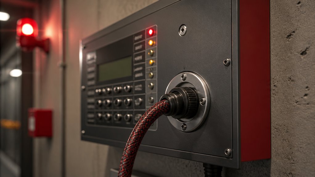
What SLC Means in Fire Alarm Systems?
In fire alarm systems, SLC stands for Signaling Line Circuit, which serves as the primary communication pathway between the fire alarm control panel and connected devices.
You’ll find SLCs in addressable or intelligent fire alarm systems, where they enable two-way communication. This circuit carries data and commands, allowing devices like smoke detectors, heat detectors, manual pull stations, and control modules to report alarms, troubles, and supervisory signals.
Unlike traditional Initiating Device Circuits (IDCs), SLCs support device-specific reporting, improving system visibility and troubleshooting. Typically wired as a two-wire loop, the SLC often carries both power and communication signals.
You’ll rely on the SLC’s capability to connect multiple device types on one loop for efficient, detailed monitoring and control throughout the fire alarm system. This device-level monitoring enhances maintenance efficiency and reduces false alarms.
How SLC Communicates in Addressable Panels?
The Signaling Line Circuit (SLC) in addressable panels actively manages two-way communication by sending digital signals between the control panel and each device on the loop.
It uses a single pair of wires to transmit both power and data, enabling devices to report status, alarms, or faults individually.
Each device on the SLC has a unique address, allowing the panel to poll and receive information from specific points, ensuring precise identification of events.
Communication occurs in a continuous loop or data loop configuration, which enhances reliability by allowing signals to traverse in both directions.
This arrangement supports real-time monitoring and rapid response, improving system diagnostics and event management without requiring separate wiring for each device.
The digital binary communication over loop wiring also reduces installation complexity and time, especially for larger buildings.
Common Addressable Devices on an SLC Loop
When you work with an SLC loop, you’ll find a variety of addressable devices designed to communicate critical fire alarm information directly to the control panel.
Common devices include smoke detectors that sense airborne particles and heat detectors that monitor temperature changes.
Manual pull stations enable manual alarm initiation.
Control modules on the loop can activate external equipment like door holders or elevator recall systems.
Notification appliances, such as horns and strobes, are often controlled through dedicated modules on the SLC, allowing precise activation.
Each device has a unique address, enabling the panel to identify its exact location and status.
This device-level communication enhances system monitoring, diagnostics, and response, making the SLC loop essential for modern, intelligent fire alarm systems.
Similar to how a security system uses motion detection to trigger alerts and conserve resources, the SLC loop optimizes communication efficiency by addressing each device individually.
Comparing SLC and IDC Wiring in Fire Alarm Systems
You’ll notice that SLC wiring uses a two-wire loop that supports both power and data. Pretty neat, right? On the other hand, IDC wiring typically involves simpler, zone-based connections.
One of the cool things about SLC is that it enables two-way communication. This means the panel can pinpoint the status of specific devices. In contrast, IDC provides more basic signaling. Before troubleshooting or testing any wiring system, it is crucial to contact authorities and place the system in test mode to prevent false alarms and unnecessary dispatches.
Wiring Differences Explained
Understand how SLC and IDC wiring differ to optimize your fire alarm system’s design and functionality.
SLC wiring typically uses a two-wire loop that carries both power and data. This enables addressable devices to communicate with the control panel individually.
IDC wiring, on the other hand, usually consists of simpler circuits connecting initiating devices in a non-addressable, zone-based manner.
Key wiring differences include:
SLC often requires shielded twisted-pair cables to reduce interference. IDC uses standard wiring.
SLC supports a loop configuration for continuous communication. IDC is wired in parallel or series.
SLC wiring carries both power and data on the same pair. IDC wiring generally supplies power only.
SLC enables device-level monitoring. IDC wiring provides only zone-level status.
These distinctions impact system scalability and troubleshooting precision. Proper installation ensures compliance with local codes and effective monitoring for rapid response.
Communication Capabilities Comparison
Although both SLC and IDC wiring serve essential roles in fire alarm systems, their communication capabilities differ markedly.
SLC supports two-way communication, enabling the control panel to identify individual devices and their exact status: alarms, troubles, or supervisory signals. This level of detail lets you pinpoint issues and respond faster.
In contrast, IDC wiring provides basic, one-way signaling from initiating devices to the panel. It often groups devices by zone rather than individually and lacks the addressable features that SLC offers.
Additionally, SLC circuits typically use a loop configuration with shielded twisted-pair cables to minimize interference. IDC wiring is simpler and less data-driven.
When designing or troubleshooting, you’ll appreciate SLC’s advanced communication capabilities for larger, more sophisticated fire alarm systems.
Proper wiring practices, including secure connections and color-coded wiring, are essential to ensure reliable interconnected alarms and system functionality.
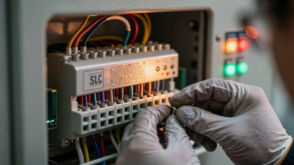
Typical Wiring and Cable Requirements for SLC
When installing an SLC, selecting the proper wiring and cable is essential to guarantee reliable communication and power delivery between the fire alarm control panel and connected devices.
You’ll want cables that support both data and power transmission without interference or signal loss.
Typically, SLC wiring involves:
- Shielded twisted-pair cable to minimize electromagnetic interference.
- Two-conductor cable to carry power and communication signals.
- Compliance with National Electrical Code (NEC) and local fire safety standards.
- Proper cable gauge, often 18 or 16 AWG, to make certain voltage drop stays within limits.
Choosing cables that meet these requirements helps maintain system integrity.
It ensures accurate device communication and supports the overall reliability of your addressable fire alarm system.
Additionally, verifying the NEC compliance of your wiring setup is critical to avoid circuit overloads and ensure system safety.
Why Most SLC Circuits Use Two Wires?
You’ll find that most SLC circuits use two wires, and there’s a good reason for that.
By combining power and communication on a single path, it really simplifies things. This integration helps reduce complexity and saves time during installation.
Plus, using just two wires supports the loop configuration that’s so crucial for addressable device communication. So, it’s not just about cutting down on wires; it’s also about making sure everything works smoothly together.
This design also ensures reliable power delivery and communication even if one part of the loop experiences an issue, enhancing the interconnected system reliability.
Power And Communication Integration
Understanding why most Signaling Line Circuits (SLCs) use two wires is key to grasping how fire alarm systems efficiently integrate power and communication.
The two-wire design allows the same pair to transmit data signals and supply power to connected devices. This reduces complexity while maintaining system reliability.
This integration supports continuous device operation and real-time communication with the control panel.
In practice, this means you benefit from:
- A combined pathway for power and data, minimizing wiring needs.
- Consistent voltage supply ensuring device readiness.
- Two-way communication enabling device status reports and commands.
- Simplified fault detection by monitoring loop continuity.
This dual-function wiring optimizes performance while maintaining the high safety standards required in fire alarm systems. Proper wiring and mounting are essential to prevent tampering or signal loss, ensuring reliable operation.
Simplified Wiring And Installation
Simplified wiring schemes make installation more efficient by reducing cable complexity and labor time.
Most Signaling Line Circuits (SLCs) use two-wire loops because these wires simultaneously carry both power and data communication. By combining functions, you avoid running separate cables for power and signaling. This streamlines your wiring layout and reduces installation costs.
The two-wire design also supports loop topology, improving system reliability through continuous communication. Even if one segment is damaged, signals can travel the alternate path.
Using shielded twisted-pair cables further minimizes electromagnetic interference, ensuring clear data transmission. This approach enables you to connect multiple addressable devices on a single circuit, simplifying your system architecture.
Troubleshooting becomes more straightforward by pinpointing device-specific events without excessive wiring complexity.
Additionally, following manufacturer instructions and local codes ensures reliable and code-compliant installation of interconnected fire alarm systems.
How SLC Improves Fire Alarm Monitoring and Response?
Enhancing fire alarm monitoring and response hinges on the Signaling Line Circuit’s ability to provide detailed, device-level information. You rely on the SLC to pinpoint the exact device triggering an alarm, enabling faster, targeted action.
It supports two-way communication, so devices can report status changes in real time. This detailed feedback improves system visibility and troubleshooting accuracy.
With SLC, you get:
- Precise identification of alarms, troubles, and supervisory signals by device
- Continuous communication loop ensuring consistent device status updates
- Integration of multiple device types on a single circuit for all-encompassing coverage
- Enhanced data transmission reducing false alarms and response delays
Design Considerations for Fire Alarm Systems Using SLC
When designing fire alarm systems that use an SLC, you must carefully plan the wiring layout and device placement to assure dependable communication and power delivery.
Use a looped two-wire circuit. Consider cable type; shielded twisted-pair can reduce interference.
Position devices to minimize signal degradation and allow straightforward troubleshooting. Balance device quantity per loop to avoid overloads and maintain responsiveness.
| Consideration | Recommendation |
|---|---|
| Wiring Layout | Use looped two-wire circuit |
| Cable Type | Shielded twisted-pair |
| Device Placement | Minimize interference zones |
Proper design maximizes SLC performance, assuring reliable device communication, accurate location tracking, and efficient system response during alarms or troubles.
Frequently Asked Questions
Can SLC Circuits Be Expanded After Initial Fire Alarm Installation?
Yes, you can expand SLC circuits after the initial fire alarm installation, but it depends on the system’s capacity and design.
Most addressable panels support adding more devices to the existing loop or creating additional loops.
You’ll need to verify the panel’s device limit and make certain proper wiring and power considerations.
Expanding allows you to integrate new detectors or modules while maintaining communication and monitoring capabilities across the system.
How Does SLC Handle Device Failures or Communication Loss?
Just like a telegram line in the 1800s, the SLC continuously monitors communication integrity.
When a device fails or communication is lost, the SLC detects the interruption and signals a trouble condition to you. This lets you identify the exact device or segment affected.
The system maintains two-way communication by isolating faults, ensuring the rest of the loop remains operational. This allows you to troubleshoot without compromising the entire fire alarm network.
Are There Specific Maintenance Routines for SLC Wiring and Devices?
Yes, you should regularly inspect SLC wiring for physical damage, corrosion, and secure connections to ensure reliable communication.
Perform continuity and resistance tests to detect faults or shorts. Test devices on the circuit for proper signaling and response.
Keep firmware updated on addressable modules. Also, clean devices to avoid dust buildup that can affect sensors.
Routine maintenance ensures your SLC network operates without communication loss or device failures.
What Are Common Troubleshooting Steps for SLC Communication Issues?
To troubleshoot SLC communication issues, first check wiring continuity and guarantee proper polarity.
Inspect for damaged or loose connections and verify cable integrity using a multimeter.
Confirm device addressing and panel configuration settings.
Look for any shorts or open circuits affecting the loop.
Use the control panel’s diagnostics to identify trouble signals or device failures.
Finally, replace faulty devices or cables and retest the loop for restored communication.
Can SLC Technology Integrate With Building Automation Systems?
Think of SLC technology as the nervous system that can connect seamlessly with building automation systems.
You can integrate it using compatible gateways or protocols like BACnet or Modbus, allowing fire alarm data to communicate with HVAC, lighting, and security systems.
This integration boosts centralized control and real-time monitoring, making your building smarter and more responsive to emergencies.
It also maintains precise, two-way communication between devices and automation platforms.
Know How SLC Improves Fire Alarm Communication
Understanding that SLC stands for Signaling Line Circuit is essential in fire alarm systems.
Did you know over 70% of modern addressable fire panels use SLC loops for device communication?
This two-wire circuit enhances monitoring and response by enabling continuous device supervision and fault detection.
By grasping SLC’s role, you can design more reliable, efficient fire alarm systems that improve safety and reduce false alarms.
This makes your installations both smarter and more effective.